Misc
Here are bits and pieces of ideas that are being developed.
Converting a tmp117 to a tmp114
Problem
You have a tmp114 temperature sensor and you need a driver for it.
Solution
Find a similar driver and convert it to the tmp114.
Let’s first see if there is a driver for it already. Run the following on the bone using the tab key in place of <tab>.
bone$ modinfo tmp<tab><tab>
tmp006  tmp007  tmp102  tmp103  tmp108  tmp401  tmp421  tmp513
bone$ modinfo tmp
Here you see a list of modules that match tmp, unfortunately tmp114 is not there. Let’s see if there are any matches in /lib/modules.
bone$ find /lib/modules/ -iname "*tmp*"
/lib/modules/5.10.168-ti-arm64-r104/kernel/drivers/iio/temperature/tmp006.ko.xz
/lib/modules/5.10.168-ti-arm64-r104/kernel/drivers/iio/temperature/tmp007.ko.xz
/lib/modules/5.10.168-ti-arm64-r104/kernel/drivers/hwmon/tmp103.ko.xz
/lib/modules/5.10.168-ti-arm64-r104/kernel/drivers/hwmon/tmp421.ko.xz
/lib/modules/5.10.168-ti-arm64-r104/kernel/drivers/hwmon/tmp108.ko.xz
/lib/modules/5.10.168-ti-arm64-r104/kernel/drivers/hwmon/tmp513.ko.xz
/lib/modules/5.10.168-ti-arm64-r104/kernel/drivers/hwmon/tmp401.ko.xz
/lib/modules/5.10.168-ti-arm64-r104/kernel/drivers/hwmon/tmp102.ko.xz
Looks like the same list, but here we can see what type of driver it is, either hwmon or iio. hwmon is an older harware monitor. iio is the newer, and prefered, Industrial IO driver. Googling tmp006 and tmp007 shows that they are Infrared Thermopile Sensors, not the same at the tmp114. (Google it). Let’s keep looking for a more compatible device.
Browse over to http://kernel.org to see if there are tmp114 drivers in the newer versions of the kernel. The first line in the table is mainline. Click on the browse link on the right. Here you will see the top level of the Linux sourse tree for the mainline version of the kernel. Click on drivers and then iio. Finally, since tmp114 is a temperture sensor, click on temperature. Here you see all the source code for the iio temperature drivers for the mainline version of the kernel. We’ve seen tmp006 and tmp007 as before, tmp117 is new. Maybe it will work. Click on tmp117.c to see the code. Looks like it also works for the tmp116 too. Let’s try convering it to work with the tmp114.
A quick way to copy the code to the bone is to right-click on the plain link and select Copy link address. Then, on the bone enter wget and paste the link. Mine looks like the following, yours will be similar.
bone$ wget https://git.kernel.org/pub/scm/linux/kernel/git/torvalds/linux.git/plain/drivers/iio/temperature/tmp117.c?h=v6.4-rc7
bone$ mv 'tmp117.c?h=v6.4-rc7' tmp117.c
bone$ cp tmp117.c tmp114.c
The mv command moves the downloaded file to a usable name and the cp copies to a new file with the new name.
Compiling the module
Next we need to compile the driver. To do this we need to load the corresponding header files for the version of the kernel that’s beening run.
bone$ uname -r
5.10.168-ti-arm64-r105
Here you see which version I’m running, yours will be similar. Now load the headers.
bone$ sudo apt install linux-headers-`uname -r`
Next create a Makefile. Put the following in a file called Makefile.
 1obj-m += tmp114.o
 2
 3KDIR ?= /lib/modules/$(shell uname -r)/build
 4PWD := $(CURDIR)
 5
 6all:
 7        make -C $(KDIR) M=$(PWD) modules
 8
 9clean:
10        make -C $(KDIR) M=$(PWD) cleanobj-m += tmp114.o
11
12KDIR ?= /lib/modules/$(shell uname -r)/build
13PWD := $(CURDIR)
14
15all:
16        make -C $(KDIR) M=$(PWD) modules
17
18clean:
19        make -C $(KDIR) M=$(PWD) clean
Now you are ready to compile:
bone$ make
make -C /lib/modules/5.10.168-ti-arm64-r105/build M=/home/debian/play modules
make[1]: Entering directory '/usr/src/linux-headers-5.10.168-ti-arm64-r105'
CC [M]  /home/debian/play/tmp114.o
/home/debian/play/tmp114.c: In function ‘tmp117_identify’:
/home/debian/play/tmp114.c:150:7: error: implicit declaration of function ‘i2c_client_get_device_id’; did you mean ‘i2c_get_device_id’? [-Werror=implicit-function-declaration]
150 |  id = i2c_client_get_device_id(client);
    |       ^~~~~~~~~~~~~~~~~~~~~~~~
    |       i2c_get_device_id
/home/debian/play/tmp114.c:150:5: warning: assignment to ‘const struct i2c_device_id *’ from ‘int’ makes pointer from integer without a cast [-Wint-conversion]
150 |  id = i2c_client_get_device_id(client);
    |     ^
cc1: some warnings being treated as errors
make[2]: *** [scripts/Makefile.build:286: /home/debian/play/tmp114.o] Error 1
make[1]: *** [Makefile:1822: /home/debian/play] Error 2
make[1]: Leaving directory '/usr/src/linux-headers-5.10.168-ti-arm64-r105'
make: *** [Makefile:7: all] Error 2
Well, the good news is, it is compiling, that means it found the correct headers. But now the work begins converting to the tmp114.
Converting to the tmp114
You are mostly on your own for this part, but here are some suggestions:
First get it to compile without errors. In this case, the function at line 150 isn’t defined. Try commenting it out and recompiling.
Once it’s compiling without errors, try running it. First open another window and login to beagle. Then run:
bone$ dmesg -Hw
This will display the kernel messages. The -H put them in human readable form, and the -w waits for more messages.
Next, “insert” it in the running kernel:
bone$ sudo insmod tmp114.ko
If all worked you shouldn’t see any messages, either after the command or in the dmesg window. If you want to insert the module again, you will have to remove it first. Remove with:
bone$ sudo rmmod tmp114
Now we need to tell the kernel we have an I2C device and which bus and which address.
Finding your I2C device
Each I2C device appears at a certain address on a given bus. My device is on bus 3, so I run:
bone$ i2cdetect -y -r 3
    0  1  2  3  4  5  6  7  8  9  a  b  c  d  e  f
00:                         -- -- -- -- -- -- -- --
10: -- -- -- -- -- -- -- -- -- -- -- -- -- -- -- --
20: -- -- -- -- -- -- -- -- -- -- -- -- -- -- -- --
30: -- -- -- -- -- -- -- -- -- -- -- -- -- -- -- --
40: -- -- -- -- -- -- -- -- -- -- -- -- -- 4d -- --
50: -- -- -- -- -- -- -- -- -- -- -- -- -- -- -- --
60: -- -- -- -- -- -- -- -- -- -- -- -- -- -- -- --
70: -- -- -- -- -- -- -- --
This shows there is a device at address 0x4d. If you don’t know your bus number, just try a few until you find it.
The temperature is in register 0 for my device and it’s 16 bits (one word), it is read with:
bone$  i2cget -y 3 0x4d 0 w
0xb510
The tmp114 swaps the two bytes, so the real temperature is 0x10b5, or so. You need to look up the datawsheet to learn how to comvert it.
Registers and IDs
Each I2C device has a number of internal registers that interact with the device. The tmp114 uses different register numbers than the tmp117, so you need to change these values. To do this, Google for the data sheets for each and look them up. I found them at: https://www.ti.com/lit/gpn/tmp114 and https://www.ti.com/lit/gpn/tmp117.
Creating a new device
Once you’ve converted the module for the tmp114 and inserted it, you can now create a new device.
bone$ cd /sys/class/i2c-adapter/i2c-3
bone$ sudo chgrp gpio *
bone$ sudo chmod g+w *
bone$ ls -ls
total 0
0 --w--w---- 1 root gpio 4096 Jun 22 18:24 delete_device
0 lrwxrwxrwx 1 root root    0 Jan  1  1970 device -> ../../20030000.i2c
0 drwxrwxr-x 3 root gpio    0 Jun 22 18:20 i2c-dev
0 -r--rw-r-- 1 root gpio 4096 Jun 22 18:20 name
0 --w--w---- 1 root gpio 4096 Jun 22 18:20 new_device
0 lrwxrwxrwx 1 root root    0 Jan  1  1970 of_node -> ../../../../../firmware/devicetree/base/bus@f0000/i2c@20030000
0 drwxrwxr-x 2 root gpio    0 Jun 22 18:20 power
0 lrwxrwxrwx 1 root root    0 Jan  1  1970 subsystem -> ../../../../../bus/i2c
0 -rw-rw-r-- 1 root gpio 4096 Jun 22 18:20 uevent
The first line changes to the directory to where we can create the new device. The final 3 in the path is for bus 3, your milage may vary. We then change the group to gpio and give it write permission. You only need to do this once.
Now make a new device.
bone$ echo tmp114 0x4d > new_device
Look in the demsg window and you should see:
[Jun22 19:24] tmp114 3-004d: tmp114_identify id (0x1114)
[  +0.000027] tmp114 3-004d: tmp114_probe id (0x1114)
[  +0.000502] i2c i2c-3: new_device: Instantiated device tmp114 at 0x4d
It’s been found! Let’s see what it knows about it.
bone$ iio_info
Library version: 0.24 (git tag: v0.24)
...
        iio:device1: tmp114
                1 channels found:
                        temp:  (input)
                        2 channel-specific attributes found:
                                attr  0: raw value: 4257
                                attr  1: scale value: 7.812500
                No trigger on this device
I’ve left out some of the lines, at the bottom you see the tmp114, and two values (raw and scale) that were read from it. Let’s read them ourselves. Do an ls and you’ll see a new directory, 3-004d. This is address 0x4d on bus 3, just what we wanted.
bone$ cd 3-004d/iio:device1
bone$ ls
dev  in_temp_raw  in_temp_scale  name  power  subsystem  uevent
bone$ cat in_temp_raw
4275
You’ll have to look in the datasheet to learn how to convert the temperature.
If you try to run i2cget again, you’ll get an error:
bone$ i2cget -y 3 0x4d 0 w
Error: Could not set address to 0x4d: Device or resource busy
This is because the module is using it. Delete the device and you’ll have access again.
bone$ echo 0x4d > /sys/class/i2c-adapter/i2c-3/delete_device
bone$ i2cget -y 3 0x4d 0 w
0x8e10
You should also see a message in dmesg.
Documenting with Sphinx
Problem
You want to add or update the Beagle documentation.
Solution
BeagleBoard.org uses the Sphinx Python Documentation Generator and the rst markup language.
Here’s what you need to do to fork the repository and render a local copy of the documentation. Browse to https://docs.beagleboard.org/latest/ and click on the Edit on GitLab button on the upper-right of the page. Clone the repository.
bash$ git clone git@git.beagleboard.org:docs/docs.beagleboard.io.git
bash$ cd docs.beagleboard.io
Then run the following to load the code submodule
bash$ git submodule update --init
Now, sync changes with upstream:
bone$ git remote add upstream https://git.beagleboard.org/docs/docs.beagleboard.io.git
bone$ git fetch upstream
bone$ git pull upstream main
Downloading Sphinx
Run the following to download Sphinx. Note: This will take a while, it loads some 6G bytes.
bone$ sudo apt update
bone$ sudo apt upgrade
bone$ sudo apt install -y \
    make git wget \
    doxygen graphviz librsvg2-bin\
    texlive-latex-base texlive-latex-extra latexmk texlive-fonts-recommended \
    python3 python3-pip \
    python3-sphinx python3-sphinx-rtd-theme python3-sphinxcontrib.svg2pdfconverter \
    python3-pil \
    imagemagick-6.q16 librsvg2-bin webp \
    texlive-full texlive-latex-extra texlive-fonts-extra \
    fonts-freefont-otf fonts-dejavu fonts-dejavu-extra fonts-freefont-ttf
bone$ python3 -m pip install --upgrade pip
bone$ pip install -U sphinx_design
bone$ pip install -U sphinxcontrib-images
bone$ pip install -U sphinx-serve
These instructions came from lorforlinux on the Beagleboard Slack channel.
Now go to the cloned docs.beagleboard.io repository folder and do the following. To clean build directory:
bone$ cd docs.beagleboard.io
bone$ make clean
To generate HTML output of docs:
bone$ make html
To generate PDF output of docs:
bone$ make latexpdf
To preview docs on your local machine:
bone$ sphinx-serve
Then point your browser to localhost:8081.
Tip
You can keep the sphinx-serve running until you clean the build directory using make clean. Warnings will be hidden after first run of make html or make latexpdf, to see all the warnings again just run make clean before building HTML or PDF
Creating A New Book
Create a new book folder here: https://git.beagleboard.org/docs/docs.beagleboard.io/-/tree/main/books
Create rst files for all the chapters in there respective folders so that you can easily manage media for that chapter as shown here: https://git.beagleboard.org/docs/docs.beagleboard.io/-/tree/main/books/pru-cookbook
Create an index.rst file in the book folder and add a table of content (toc) for all the chapters. For example see this file: https://git.beagleboard.org/docs/docs.beagleboard.io/-/raw/main/books/pru-cookbook/index.rst
Add the bookname/index.rst reference in the main index file as well: https://git.beagleboard.org/docs/docs.beagleboard.io/-/raw/main/books/index.rst
At last you have to update the two files below to render the book in HTML and PDF version of the docs respectively: https://git.beagleboard.org/docs/docs.beagleboard.io/-/raw/main/index.rst https://git.beagleboard.org/docs/docs.beagleboard.io/-/raw/main/index-tex.rst
Running Sparkfun’s qwiic Python Examples
Many of the Sparkfun qwiic devices have Python examples showing how to use them. Unfortunately the examples assume I2C bus 1 is used, but the qwiic bus on the Play is bus 5. Here is a quick hack to get the Sparkfun Python examples to use bus 5. I’ll show it for the Joystick, but it should work for the others as well.
First, browse to Sparkfun’s qwiic Joystick page, https://www.sparkfun.com/products/15168 and click on the DOCUMENTS tab and then on Python Package. Follow the pip instillation instructions (sudo pip install sparkfun-qwiic-joystick)
Next, uninstall the current qwiic I2C package.
bone$ sudo pip uninstall sparkfun-qwiic-i2c
Then clone the Qwiic I2C repo:
bone$ git clone git@github.com:sparkfun/Qwiic_I2C_Py.git
bone$ cd Qwiic_I2C_Py/qwiic_i2c
Edit linux_i2c.py and go to around line 62 and change it to:
iBus = 5
Next, cd up a level to the Qwiic_I2C_Py directory and reinstall
bone$ cd ..
bone$ sudo python setup.py install
Finally, run one of the Joystick examples. If it isn’t using bus 5, try reinstalling setup.py again.
Controlling LEDs by Using SYSFS Entries
Problem
You want to control the onboard LEDs from the command line.
Solution
On Linux, everything is a file that is, you can access all the inputs and outputs, the LEDs,
and so on by opening the right file and reading or writing to it. For example, try the following:
bone$ cd /sys/class/leds/
bone$ ls
beaglebone:green:usr0  beaglebone:green:usr2
beaglebone:green:usr1  beaglebone:green:usr3
What you are seeing are four directories, one for each onboard LED. Now try this:
bone$ cd beaglebone\:green\:usr0
bone$ ls
brightness  device  max_brightness  power  subsystem  trigger  uevent
bone$ cat trigger
none nand-disk mmc0 mmc1 timer oneshot [heartbeat]
    backlight gpio cpu0 default-on transient
The first command changes into the directory for LED usr0, which is the LED closest to the edge of the board. The [heartbeat] indicates that the default trigger (behavior) for the LED is to blink in the heartbeat pattern. Look at your LED. Is it blinking in a heartbeat pattern?
Then try the following:
bone$ echo none > trigger
bone$ cat trigger
[none] nand-disk mmc0 mmc1 timer oneshot heartbeat
    backlight gpio cpu0 default-on transient
This instructs the LED to use none for a trigger. Look again. It should be no longer blinking.
Now, try turning it on and off:
bone$ echo 1 > brightness
bone$ echo 0 > brightness
The LED should be turning on and off with the commands.
Controlling GPIOs by Using SYSFS Entries
Problem
You want to control a GPIO pin from the command line.
Solution
Controlling LEDs by Using SYSFS Entries introduces the sysfs. This recipe shows how to read and write a GPIO pin.
Reading a GPIO Pin via sysfs
Suppose that you want to read the state of the P9_42 GPIO pin. (Reading the Status of a Pushbutton or Magnetic Switch (Passive On/Off Sensor) shows how to wire a switch to P9_42.) First, you need to map the P9 header location to GPIO number using Mapping P9_42 header position to GPIO 7, which shows that P9_42 maps to GPIO 7.
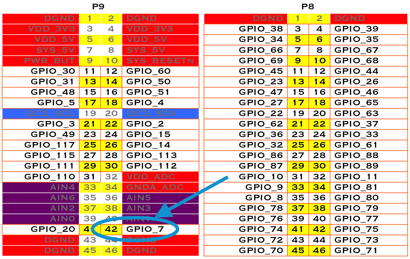
Fig. 336 Mapping P9_42 header position to GPIO 7
Next, change to the GPIO sysfs directory:
bone$ cd /sys/class/gpio/
bone$ ls
export  gpiochip0  gpiochip32  gpiochip64  gpiochip96  unexport
The ls command shows all the GPIO pins that have be exported. In this case, none have, so you see only the four GPIO controllers. Export using the export command:
bone$ echo 7 > export
bone$ ls
export  gpio7  gpiochip0  gpiochip32  gpiochip64  gpiochip96  unexport
Now you can see the gpio7 directory. Change into the gpio7 directory and look around:
bone$ cd gpio7
bone$ ls
active_low  direction  edge  power  subsystem  uevent  value
bone$ cat direction
in
bone$ cat value
0
Notice that the pin is already configured to be an input pin. (If it wasn’t already configured that way, use echo in > direction to configure it.) You can also see that its current value is 0—that is, it isn’t pressed. Try pressing and holding it and running again:
bone$ cat value
1
The 1 informs you that the switch is pressed. When you are done with GPIO 7, you can always unexport it:
bone$ cd ..
bone$ echo 7 > unexport
bone$ ls
export  gpiochip0  gpiochip32  gpiochip64  gpiochip96  unexport
Writing a GPIO Pin via sysfs
Now, suppose that you want to control an external LED. Toggling an External LED shows how to wire an LED to P9_14. Mapping P9_42 header position to GPIO 7 shows P9_14 is GPIO 50. Following the approach in Controlling GPIOs by Using SYSFS Entries, enable GPIO 50 and make it an output:
bone$ cd /sys/class/gpio/
bone$ echo 50 > export
bone$ ls
gpio50  gpiochip0  gpiochip32  gpiochip64  gpiochip96
bone$ cd gpio50
bone$ ls
active_low  direction  edge  power  subsystem  uevent  value
bone$ cat direction
in
By default, P9_14 is set as an input. Switch it to an output and turn it on:
bone$ echo out > direction
bone$ echo 1 > value
bone$ echo 0 > value
The LED turns on when a 1 is written to value and turns off when a 0 is written.